Why One Good Sample Is Not Enough: First–Middle–Last Inspection for Decorative Profiles
A well-finished sample proves that an acceptable result is possible. It does not prove that the same result will continue across a production batch.
This distinction matters when processing skeleton-door profiles, decorative mouldings, door casing strips, and furniture trim. These workpieces are often long, narrow, and visible after installation. Small changes in feeding, bonding, trimming, or surface handling can become obvious when several finished profiles are placed together.
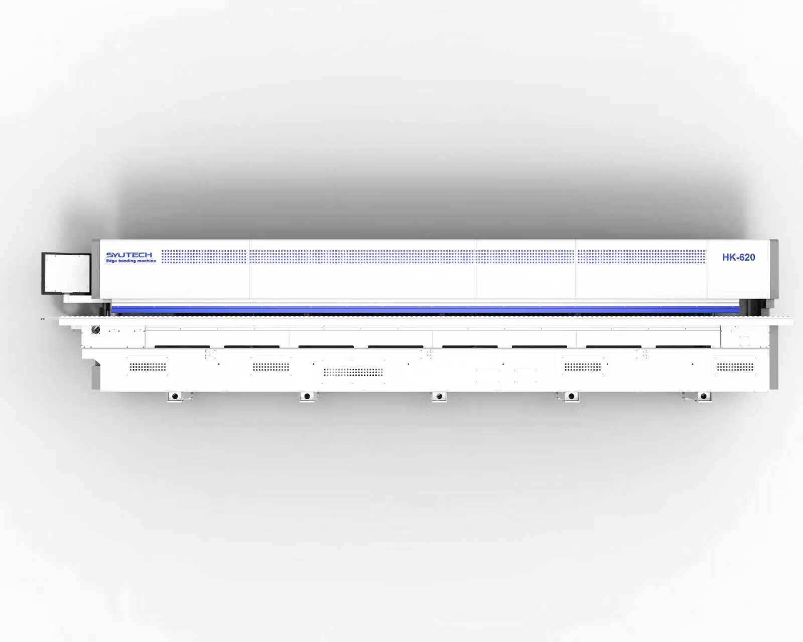
For buyers evaluating the HK620 profile edge banding machine, the more useful question is not simply, “Can the machine produce one good piece?” The question is, “Can the agreed process maintain an acceptable result from the beginning to the middle and end of a representative run?”
The Difference Between a Demonstration and a Batch Check
A demonstration normally answers a narrow question: can a selected workpiece pass through the proposed process and reach an acceptable appearance?
A batch check goes further. It examines whether the result remains consistent while normal production variables are present. These may include material variation, workpiece length, profile geometry, operator adjustments, changeovers, adhesive condition, and interruptions.
This does not mean every factory needs the same sample quantity or test duration. Those details must be agreed for the actual product. The important principle is that acceptance should cover more than the best individual piece.
The first–middle–last method provides a practical structure:
- First sample: confirms setup and establishes the approved reference.
- Middle sample: checks whether the process remains stable after continued operation.
- Final sample: checks whether the accepted appearance and geometry are still present at the end of the run.
1. Define the Reference Before Processing
Inspection begins before the machine starts. The buyer and supplier should identify the workpiece, base material, surface material, edge-banding material, adhesive requirement, and visible faces.
They should also agree on what will be inspected. Depending on the product, this may include:
- Edge-material position and coverage.
- Glue-line appearance.
- Trimming quality and visible tool marks.
- Surface scratches, pressure marks, or deformation.
- Front and rear end condition.
- Profile geometry after processing.
- Fit with the next machining or assembly stage.
- Visual consistency when several profiles are placed together.
If a numerical tolerance has not been confirmed by the buyer’s technical requirements, it should not be invented for the report. Record the agreed visual or functional reference and identify any item that still requires technical confirmation.
2. Inspect and Label the First Sample
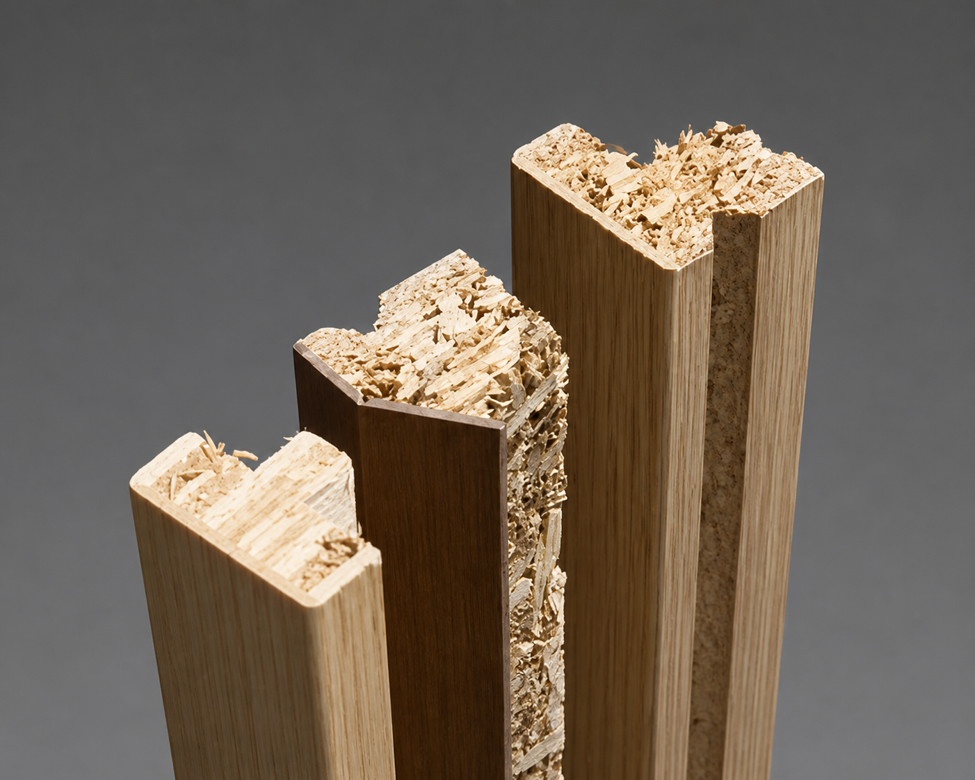
The first accepted piece becomes the reference for the rest of the run. It should not be selected without recording the setup conditions that produced it.
Label the sample with the test date, workpiece code, material batch, and sequence position. Photograph the complete workpiece and any critical details under consistent lighting. Record adjustments made before acceptance.
The first sample should answer:
- Is the workpiece feeding and tracking as intended?
- Is the edge material correctly positioned?
- Are the visible surfaces free from unacceptable damage?
- Are bonding, trimming, and end conditions acceptable?
- Does the piece fit the next process or final assembly requirement?
Do not discard unsuccessful setup pieces from the record. They help explain the actual adjustment process and prevent the final report from showing only a selected result.
3. Check the Middle of the Run Without Changing the Standard
The middle sample is useful because some problems are not visible immediately after setup. A process may drift as more pieces are fed, as materials vary, or after an operator makes a correction.
Select the middle sample according to a sequence agreed before the test. Avoid choosing whichever piece looks best. Compare it directly with the accepted first sample using the same inspection position and lighting.
Record any difference in:
- Feeding marks or workpiece movement.
- Edge alignment.
- Glue-line visibility.
- Trimming and corner condition.
- Surface finish.
- Profile geometry.
If an adjustment is required, record the reason, time, and result. The samples before and after that adjustment should remain identifiable.
4. Use the Final Sample to Confirm End-of-Run Consistency
The final sample should be inspected against the same criteria used for the first and middle samples. Changing the acceptance standard after seeing the results makes the report less useful.
Compare all three sequence points side by side. The goal is not to claim that no variation exists. The goal is to determine whether observed variation remains within the buyer’s agreed product standard.
The final sample should also be reviewed together with any record of stops, material changes, adjustments, or abnormal events. If the process was interrupted, record whether it returned to the accepted condition after restart.
5. Inspect the Profiles Together, Not Only One by One
Decorative components are often installed in groups. Colour direction, surface relationship, glue-line appearance, and trimming differences may become more visible when profiles are assembled or placed next to one another.
Arrange the first, middle, and final samples in the same orientation and under the same light. If possible, place them in the relationship used in the final door, wall, cabinet, or furniture assembly.
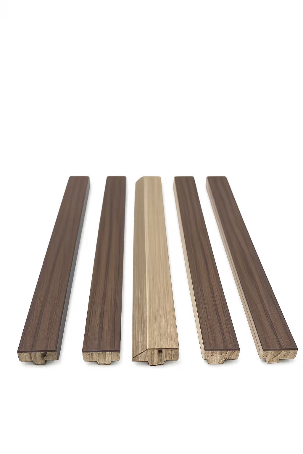
This group inspection can reveal differences that are easy to miss when each part is reviewed separately.
6. Record Interruptions and Recovery
Stable production includes the ability to identify and recover from normal problems. If the test includes a stop, material change, or adjustment, the record should show what happened and how the accepted condition was restored.
Capture:
- The reason for the interruption.
- The affected sample numbers.
- The adjustment or corrective action.
- The first piece produced after restart.
- Comparison with the original accepted reference.
This information is more valuable than a general statement that the machine “runs stably.” It gives the buyer a traceable basis for training, commissioning, and later production control.
7. Keep Adhesive Conditions in the Inspection Record
Bonding results depend on the actual material and adhesive process. If PUR is part of the intended production method, it should be identified in the test record together with the relevant material combination and agreed operating conditions.
Do not transfer a result from one material system to another without confirmation. For related adhesive checks and maintenance considerations, see Edge Bander Glue Troubleshooting: Adhesive, Glue Line, and Pot Maintenance.
What a Useful Inspection Report Should Contain
A practical first–middle–last report should include:
- Test date and machine model or configuration reference.
- Workpiece codes, drawings, and material identification.
- Edge-banding material and adhesive requirement.
- Agreed inspection points.
- Photographs of the unprocessed workpiece.
- Labelled first, middle, and final samples.
- Adjustment, interruption, and recovery records.
- Side-by-side inspection photographs.
- Items accepted by both parties.
- Items requiring another test or technical confirmation.
- The next decision: proceed, revise the configuration, retest, or reject the application.
For the broader purchasing process, use the existing HK620 Buyer Verification Guide together with this batch-inspection method.
Frequently Asked Questions
Why is one good sample insufficient?
It shows that an acceptable result is possible under one set of conditions. It does not show whether the same result continues across a representative run or after normal adjustments and material variation.
How many pieces should be included in the test?
There is no universal number for every profile and factory. The buyer and supplier should agree on a representative sequence based on the real product, material mix, batch size, and purchasing risk.
What should be compared between the first, middle, and final samples?
Compare feeding marks, edge position, glue-line appearance, trimming, surface condition, end condition, geometry, and fit with the next process or assembly.
Should rejected pieces be recorded?
Yes. Rejected or borderline pieces help explain the operating window, adjustment history, and actual reason for acceptance or rejection.
Does this inspection confirm every HK620 application?
No. HK620 configuration and process suitability depend on the buyer’s actual workpiece, materials, adhesive requirement, production target, electrical requirement, and workshop conditions. These inputs require application-specific review.
Request an HK620 Workpiece Review
Send SYUTECH clear workpiece photos, a cross-section drawing or physical sample, dimensions, base and surface materials, edge-banding material, adhesive requirement, production target, destination country, voltage, and workshop layout.
Contact Wood Machinery Network for an HK620 workpiece review